Special properties of member
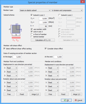
This window contains advanced properties of member.
Member type
Program uses two basic member types:
Beam |
|
Beam on elastic subsoil |
|
Additionally, it is possible to exclude compressive or tensile stresses in the member.
Subsoil parameters
The subsoil can be specified in directions of local axes 3 or 2. The subsoil is defined by Winkler-Pasternak constants C1 and C2. The constants C1 and C2 may be calculated from the general parameters of subsoil in the window "Calculation of C1 and C2". The subsoil acts as general spring, that acts both in compression and tension. As this model usually does not correspond to the real conditions, the appearance of tensile stress should be checked.
The setting "Use member width" uses the cross-section width as the width of member contact with subsoil. If not used, the contact width b may be specified manually.
The default assumption is, that the subsoil acts in the direction of the local axis 3 (against gravity). The setting "Acts in axis 3" is able to change this behaviour.
The shear effects at the member ends may be taken into the account with the help of settings "In front of member" and "Behind member".
The subsoil properties are described in the theoretical chapter "Subsoil model".
Warping prevention
The part "Rate of warping prevention" contains the setting, that affects behaviour of member in torsion. Torsion causes both the deformation of cross-section in its plane and in the perpendicular direction (parallel to the member axis). This behaviour is called warping. If the warping is not prevented in the structure, torsion induces only shear stresses and the cross-section is deformed in both directions. Such behaviour is called St.Venant torsion. If the warping is prevented, the torsion induces shear and axial stresses and such torsion is called warping torsion. Warping does not appear for all cross-sections. Warping is common mainly for steel cross-sections with warping coordinate ω and warping constant Iω greater than 0. Warping parameters can be specified only for these cross-sections.
Warping prevention can be specified with the help of the constant with the interval <0;1>, where 0 means free warping and 1 means warping absolutely prevented. The intermediate values describe combined behaviour. Three different internal forces induced by torsion may appear on members subjected to warping: St.Venant torsional moment Tt, bimoment B and warping torsional moment To. Moments Tt and To induce shear stresses in cross-section, bimoment B induces axial stress.
Shear effect
The part "Member with shear effect" may rewrite the global settings regarding the consideration of shear effect on deformations. This theoretical model with shear consideration is recommended cases, where member length isn't significantly longer than cross-section dimensions. The theoretical background is described in the chapter "Special member characteristics".
Member end conditions
This frame contains extended options for end conditions. It brings an option to specify a spring connections in any direction (not only fixed/free). The spring constant K has to be specified in this case. The buttons "Free", "Fixed" and "Elastic" will create corresponding end condition. End conditions are also described in the theoretical chapter "End conditions".
 Window "Special properties of member"